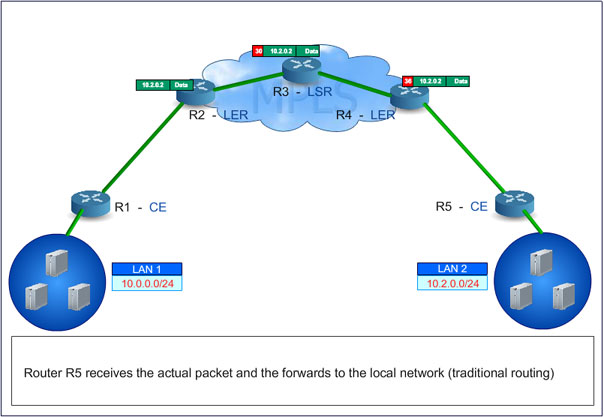
MPLS Architecture
Packet Traversal: Site A (10.2.0.0/24) – R1 – R2 (MPLS Ingress LER)-R3 (LSR) - R4 (LSR) - R5 (Egress LER) – R6 –Site B (10.0.0.0/24)
Here R1- R2- R3- R4- R5- R6 refers to routers used for packet switching operation.
MPLS Elements
- Forward Equivalence Class (FEC): This class includes a cluster of packets of a specific application forwarded in its switch path over the same pathway (with same forwarding treatment). Every packet of a particular class hold same service requirement. Every type of data traffic is assigned with a new FEC and is done only once while they enter the MPLS cloud.
- Ingress Label Edge Router (LER): It exists on the perimeter of an mpls cloud and is an entry point where the data packet originates from its source. This edge router imposes label (PUSH) and forward packets to destination through the domain. After setting up LSP and assigning labels, this ingress edge router initiates packet-forwarding process in MPLS core network.
- Egress Label Edge Router (LER): It exists on the perimeter of an mpls network and is an exit point where the data packet reaches its destination. This edge router performs label disposition or removal (POP) and forwards IP packet to destination. It disposes label from the arrived packet only when bottom-of-stack indicator identifies if the encountered label is bottom label of the stack or not.
- Label Switch Router (LSR): This router receives a labeled packet, swaps it with an outgoing one, and forwards the new packet to an appropriate interface. Depending on its location in MPLS domain, this router performs label disposition (removal, POP), label imposition (addition, PUSH) or label swapping (replacing the top label in a stack with a new outgoing label value). When the data stream (files or multimedia traffic) arrives from the access network to the MPLS core, it is segregated into separate FEC in this router. As an acknowledgement of label bindings, LSR creates entries in Label Information Base. This table comprises of I/O ports and I/O port labels indicating the label-FEC mapping.
- Label Switch Path (LSP): LSP is the path traversed by a packet from source to destination through an MPLS-enabled network. The path is simplex type or one-way characteristic. This allows packets to be switched from one edge to the other by traversing several intermediate switch routers. Every network location needs LSPs to be established for data transfer. For example, packet data from LER1 traverses among several intermediate nodes to LER2 using LSP1, then another path LSP2 is set out for packet transfer to other end directly, which is the shortest path to arrive the destination. However, path switching is derived from IGP routing information and may diverge from Interior Gateway Protocol preferred path to the target network.
MPLS Header

Picture 1-1: MPLS Header
A 32-bit MPLS header contains following field:
- Label (20 bits): It is a short fixed length field with a physically contiguous identifier, used to classify a FEC of local significance. After this classification, the packet is given a label value, which is used for packet forwarding. These labels are created based on network topology, request, and incoming traffic. Since they are associated with FEC, they undergo binding. Both the process of binding and label distribution are done by downstream routers. The labels are removed at egress and the packet is sent to destination.
- Class of Service (CoS) or EXP (Experimental) field: This 3-bit field influences queuing and discard algorithms applied to the packet when transmitted through the network. Since the CoS field has 3 bits, there are eight distinct service classes in use.
- Stack Field (S): A label stack is an ordered set of labels where each operates with a specific function. If an ingress router imposes more than one label in a single IP packet then it forms a stack of labels. Here, the bottom-of-stack indicator (S) is created to mention the end of label stack. As mentioned before, LSR swaps only the top label in a label stack. An egress LSR continues label disposition from the stack until it finds bottom-of-stack-indicator (S). After this, a route lookup takes place using IP Layer 3 header details and the switch router forwards packet towards the destination.
Bit representation of Stack Field (S):
S is ‘0’ - denotes label stack implementation is in use
S is ‘1’ - denotes bottom of the label stack
//Picture 1-2: Sample stacks - Time to Live (TTL): A TTL 8-bit field performs the same function of IP’s TTL, where the packet is discarded when TTL is ‘0’ to prevent looping in the network. Whenever a labeled packet traverses through LSR, the value is decremented by one.
Bit representation of TTL:
TTL is ‘0’ - Packet discarded
TTL is ‘-1’- Labeled packet traverses LSR - Upstream and Downstream: The concept of downstream and upstream is pivotal in understanding label distribution (control plane) and packet forwarding in MPLS domain. Both downstream and upstream are a reference to network. Data is downstream for a target network as it is the destination point. Updates pertaining to a specific prefix are always propagated upstream (routing protocol or label distribution, LDP/TDP).
//Figure 1-3 depicts downstream with target prefix 10.2.0.0/24 of path R1-R2-R3. For 10.0.0.0/24, downstream path is R3-R2-R1.
//Figure 1-5, R2 is downstream to R1 for destination 10.2.0.0/24, and R1 is downstream to R2 for target 10.0.0.0/24.
//Picture 1-3: - Label Distribution Protocol (LDP): This protocol distributes labels in a MPLS network based on the routing information from IGP. The router’s Forwarding Information Base (FIB) determines a hop-by-hop path throughout the network. Unlike traffic-engineered paths that use constraints and explicit routes to set up end-to-end Label Switched Paths, LDP is used only for signaling the best effort LSPs. LDP discovery enables a Label Switch Router to determine the potential of its peers. Basic mechanisms such as discovery and extended discovery are used to locate LSRs at link level.
Request for a free white paper on MPLS technology


